Menace Arm Rigging 101: Cantilever Mechanics, Counterweights & Speed-Rail Limits
How key grips calculate cantilever fulcrum ratios, 1-1/2" Schedule 40 aluminum Speed-Rail deflection, guy-wire triangulation, and 3:1 counterweight safety margins.
1. Cantilever Moment Equilibrium Math
Before pushing an LED head or fixture 10 feet out over actors or a dining table, calculate your required rear tail ballast using basic lever equilibrium:
Wc × Lc = (P × L) + (Wpipe × Lcg)
Where:
- P = Lamp & modifier weight at the front tip (lbs)
- L = Distance from the stand fulcrum pivot to the front tip (ft)
- **Lc** = Distance from the pivot to the rear counterweight ear (ft)
- **Wc** = Required tail counterweight (lbs)
Example Load Check: A 40 lb fixture extended 8 ft forward (L = 8 ft) with a 4 ft rear tail (Lc = 4 ft) needs (40 × 8) ÷ 4 = 80 lbs minimum just to reach neutral tipping balance—add +25–50% margin (100–120 lbs of shot/sandbags) so the tail always stays planted if a crew member bumps the lamp.
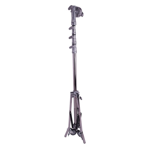
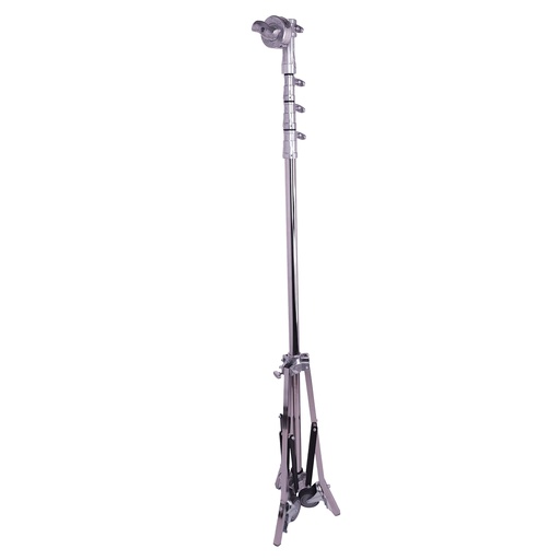
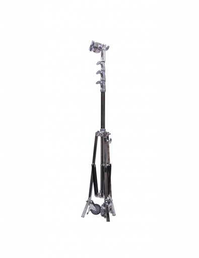
2. Diagram: Menace Arm Triangulation & Load Path
3. Speed-Rail Deflection & Tip Sag Check
Even stiff aluminum tubing bows downward as overhang L increases. Cantilever tip deflection scales with the cube of overhang length (δ = (P · L³) ÷ (3 · E · I)): doubling the arm overhang increases pipe flex 8×.
- Aluminum 6061-T6 1-1/2" Sch 40 Speed-Rail (
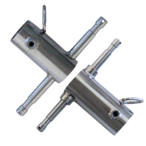
1.90"OD): Ideal up to 8–10 ft overhang with top-truss strap tensioned properly to eliminate sag. - Structural Rule 26 Violation Check: Never clamp 1-1/2" Grid Clamps directly onto thin telescopic riser tubes of a light stand—always couple through rated 1-1/8" Junior Menace Arm adapters seated inside the stand's cast receiver collar.
- Secondary Safety Cable: Loop an independent 1/8" or 1/4" aircraft safety cable (
MBS 2,000–7,000 lbs) through both the lamp yoke and the rear structural ring whenever rigging above cast or crew.
Menace Arm Rigging 101: Cantilever Mechanics, Counterweights & Speed-Rail Limits